
Electrical properties
Built to your specifications
Latest electronics and software
Electrical Resistivity
The most reliable
ER measurement
systems on the market.

Porous plate ER test allows users to desaturate core samples at different capillary pressures. The results recorded from these test can be used to calculate: Water Saturation (Sw), Resistivity (R), Formation Factor (F), Resistivity Index (RI), Cementation Exponent (m), Saturation Exponent (n), and Irreducible Water Saturation (Swi).
Like other systems manufactured by DCI the electrical resistivity systems can be configured in a wide variety of standard and custom modules to meet specific testing requirements. This includes pumps used to control confining, pore pressure, and differential pressure. There are also a number of core holder options available. Systems can be built in single cell oven type environments or up to 10 cells system allowing multiple test to be run at a time. All systems are built to simulate reservoir conditions.
DCI resistivity systems use highly accurate LCR meters to measure resistance coupled with an available switch box allowing multiple electrodes on a single sample as well as measuring multiple cells using the same data acquisition system and measurement devices. This is all controlled automatically from the computer controlled software making running tests effortless.
DCI Test Systems
982 North 675 West
North Salt Lake, Utah 84054
U.S.A.
Phone: +1 801 298-4899
Fax: +1 801 298-4875
Learn More About
Electrical Resistivity
x
2 and 4 pole measurement
DCI’s core holder design allows for both 2 and 4 pole measurements. For more custom configurations we offer designs with multiple electrical taps along the sample. With jackets available for up to 8 electrodes, DCI has an ER system that will fit your needs.
Specifications
Features
Downloads
Gallery
| Typical Electrical Resistivity Specification | |
|---|---|
| Confing Pressure: | 10,000 psi |
| Pore Pressure: | 9,500 psi |
| Temperature: | 150⁰C |
| Core Diameter: | 1", 1.5", 2", 4" |
| Core Length: | 1"-12" |
| Eletrode Measurement: | 2 & 4 pole |
| Number of Electrodes: | up to 8 |
| Differential Presssure Measurement: | Up to 200psi |
Electrical Resistivity Test Systems
These systems are designed specifically to make electrical resistivity measurements on core samples at simulated reservoir conditions. Fully saturated core samples are gradually desaturated through porous ceramic plates. A constant differential pressure is applied until a saturation equilibrium point is achieved, and electrical resistivity is measured at that equilibrium point before moving to the next desaturation point. Once the drainage cycle described above has been completed, re-saturation can be accomplished by pushing brine back into the sample (imbibition), making the associated electrical resistivity measurements. Some of the system components that make up a complete system include:
Test Cells
Test cells for these systems can be either hassler, hydrostatic, or triaxial. All of the electrically isolated core holder feature electrical feed-throughs into the test cell for 4 pole measurements. Core holders can also be equipped with thermocouples to monitor temperature of the test sample assembly. In multi-cell systems each test cell in the system can be used to conduct an independent test, at unique reservoir conditions.
Test Cell Pressure/Temperature Control System
For multi-cell systems a common pressure control cart allows each test cell in the system to be filled, pressurized, and drained separately. Pressure control to each cell can be automated. Each test cell has a pressure/temperature control panel. This panel allows the individual test cell to be isolated from the rest of the system at the desired confining pressure. It also contains the temperature controller for the test cell heaters. Other heating options include placing test cells inside of ovens.
Pore Pressure Control and Sample Desaturation System
Maintaining precise differential pressure control across the sample is critical to achieving the equilibrium points necessary for accurately calculating key parameters. Several options are available to control the de-saturation pressure across the sample. The simplest system uses a gas volume on the upstream side of the sample to maintain a constant pressure. The downstream side of the sample is simply open to atmosphere. A variation on this configuration places a gas/oil separator between the gas volume and the sample, allowing oil to be used as the displacing fluid in the sample. For tests with higher pore pressure, a back pressure control system is required. DCI’s VPA syringe pump combines the capability of a precision digital back-pressure regulator with that of a precision automated volume measurement instrument. The VPA uses feedback from a differential pressure transducer to maintain precise differential pressure across the sample. In addition, the VPA syringe pump measures the volume of pore fluid produced by the test sample to the nearest 0.0001 cc and reports the value to the automated DAQ system. A high pressure insulating coupling (HPIC) provides electrical insulation between upstream and downstream portions of the pore pressure system.
Electrical Resistivity Measurement Electronics
Typically a LCR meter is used to measure the electrical resistivity of the core sample(s). A switch box is used to measure different point on a single sample. This allows for both “2-pole” and “4-pole measurements. Other electrode configurations are available and can be measured independently. When used with multi-cell systems the switch box also switches between core holders, allowing one set of electronics for multiple core holders.
Integrated Software and Data Acquisition
Modern software integrates all of the components of the electrical resistivity system in one easy to use package. The LabVIEW based software and data acquisition allows the user to control, view and record all aspects of a test and automatically records and calculates key parameters. For multi-cell systems each test can be set up with unique logging parameters and logging intervals.


Single Cell High Frequency Resistivity System
Confining Pressure System
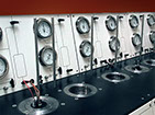
Electrical Resistivity System, Multi-Cell
Electrical Resistivity System Pore Pressure Control
Electrical Resistivity System, Multi-Cell
Electrical Resistivity System Temperature Control
Electrical Resistivity System Hydrostatic Cell
Electrical Resistivity System Oven Heating Option
CAPRI Software User Interface
Multi Cell Electrical Resistivity System Software User Interface
Electrical Resistivity System Electronics
©2022 DCI Test Systems
All Rights Reserved
Special Core Analysis
Routine Core Analysis
Rock Mechanics
Accessories
Fluid Properties
About DCI